I couldn’t justify buying a new Roomba for $1000+ just so I could have network connectivity and scheduling. The functionality just doesn’t add enough to the product to win me over and the old 500 series I have does a great job as it is.
So just in case I ever have a need for those functions, I’ve extended the life of the old beast and added the network interface and microcontroller in the most half assed way I could. And here it is…
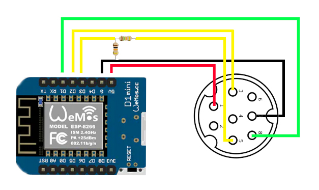
The simplest and laziest way I could find to connect my Roomba 500 series to an ESP8266 and give it a basic control interface.

PArts List
- 10kohm resistor
- 15kohm resistor
- 8 pin connector
- Wemos D1 Mini
Let’s not fart about, wire it in like the diagram above. The 15kohm and 10kohm resistors work as voltage dividers to bring down the levels of the Roombas transmit line. Apparently it never learned to use an inside voice and basically screams all the data back so loud that the ESP’s ears would bleed and it’s brain leak out before it would understand a word.
So with the voltage divider earplugs in all that’s left if the brainwork. The code at the very end of this post gives me a basic page to control the Roomba from a web browser. Just basic settings for now and more to come if I decide I need them.
The Code
|
1 2 3 4 5 6 7 8 9 10 11 12 13 14 15 16 17 18 19 20 21 22 23 24 25 26 27 28 29 30 31 32 33 34 35 36 37 38 39 40 41 42 43 44 45 46 47 48 49 50 51 52 53 54 55 56 57 58 59 60 61 62 63 64 65 66 67 68 69 70 71 72 73 74 75 76 77 78 79 80 81 82 83 84 85 86 87 88 89 90 91 92 93 94 95 96 97 98 99 100 101 102 103 104 105 106 107 108 109 110 111 112 113 114 115 116 117 118 119 120 121 122 123 124 125 126 127 128 129 130 131 132 133 134 135 136 137 138 139 140 141 142 143 144 145 146 147 148 149 150 151 152 153 154 155 156 157 158 159 160 161 162 163 164 165 166 167 168 169 170 171 172 173 174 175 176 177 178 179 180 181 182 183 184 185 186 187 188 189 190 191 192 193 194 195 196 197 198 199 200 201 202 203 204 205 206 207 208 209 210 211 212 213 214 215 216 217 218 219 220 221 222 223 224 225 226 227 228 229 230 231 232 233 234 235 236 237 238 239 240 241 242 243 244 245 246 247 248 249 250 251 252 253 254 255 256 257 258 259 260 261 262 263 264 265 266 267 268 269 270 271 272 |
String header = "HTTP/1.1 200 OK\r\nContent-Type: text/html\r\n\r\n"; String html_1 = R"=====( <!DOCTYPE html> <html> <head> <meta name='viewport' content='width=device-width, height=250px, initial-scale=1.0'/> <meta charset='utf-8'> <style> body {font-size:140%; background-color: black;} #main {display: table; margin: auto; padding: 0 10px 0 10px; } h2 {text-align:center; } .button { padding:10px 10px 10px 10px; width:100%; background-color: grey; font-size: 120%;} </style> <title>Roomba Control</title> </head> <body> <div id='main'> <font color=white><h2>Roomba Control</h2></font><br><table width=60%><tr><td></td><td> )====="; String html_2 = ""; String html_5 = ""; String html_6 = ""; String html_7 = ""; String html_8 = ""; String html_9 = ""; String html_10 = ""; String html_11 = ""; String html_12 = ""; String html_4 = R"=====( </div> </body> </html> )====="; #include <ESP8266WiFi.h> #include <SoftwareSerial.h> // change these values to match your network char ssid[] = "ItHurtsWhenIP"; // your network SSID (name) char pass[] = "Password1!"; // your network password WiFiServer server(80); String request = ""; //int LED_Pin = D1; SoftwareSerial mySerial(5,4); void setup() { pinMode(0, OUTPUT); digitalWrite(0, HIGH); mySerial.begin(19200); Serial.begin(115200); // Connecting to a WiFi network Serial.print(F("Connecting to ")); Serial.println(ssid); WiFi.begin(ssid, pass); while (WiFi.status() != WL_CONNECTED) { Serial.print("."); delay(500); } Serial.println(""); Serial.println(F("[CONNECTED]")); Serial.print("[IP "); Serial.print(WiFi.localIP()); Serial.println("]"); // start a server server.begin(); Serial.println("Server started"); startUp(); } // void setup() void startUp(){ digitalWrite(0, LOW); delay(500); digitalWrite(0, HIGH); delay(1000); digitalWrite(0, LOW); delay(200); digitalWrite(0, HIGH); delay(100); digitalWrite(0, LOW); delay(200); digitalWrite(0, HIGH); delay(100); digitalWrite(0, LOW); delay(200); digitalWrite(0, HIGH); delay(100); } void loop() { // Check if a client has connected WiFiClient client = server.available(); if (!client) { return; } // Read the first line of the request request = client.readStringUntil('\r'); Serial.print("request: "); Serial.println(request); if ( request.indexOf("WakeUp") > 0 ) { Serial.println("WakingUp"); mySerial.write(128); delay(20); mySerial.write(130); delay(20); mySerial.write(7); delay(1000); startUp(); } if ( request.indexOf("CommandMode") > 0 ) { Serial.println("CommandMode"); mySerial.write(130); delay(20); } if ( request.indexOf("Clean") > 0 ) { mySerial.write(128); delay(20); Serial.println("Clean"); mySerial.write(132); delay(20); mySerial.write(135); delay(20); } if ( request.indexOf("Dock") > 0 ) { mySerial.write(128); delay(20); Serial.println("Clean"); mySerial.write(132); delay(20); mySerial.write(143); delay(20); } if ( request.indexOf("PowerOff") > 0 ) { mySerial.write(128); delay(20); Serial.println("PowerOff"); mySerial.write(132); delay(20); mySerial.write(133); delay(20); } if ( request.indexOf("Fwd") > 0 ) { mySerial.write(128); delay(20); Serial.println("Fwd"); mySerial.write(130); delay(20); mySerial.write(145); mySerial.write(76); mySerial.write(4); mySerial.write(76); mySerial.write(4); delay(500); mySerial.write(145); mySerial.write(0); mySerial.write(0); mySerial.write(0); mySerial.write(0); } if ( request.indexOf("Back") > 0 ) { mySerial.write(128); delay(20); Serial.println("Back"); mySerial.write(130); delay(20); mySerial.write(145); mySerial.write(254); mySerial.write(12); mySerial.write(254); mySerial.write(12); delay(500); mySerial.write(145); mySerial.write(0); mySerial.write(0); mySerial.write(0); mySerial.write(0); } if ( request.indexOf("CCW") > 0 ) { mySerial.write(128); delay(20); Serial.println("CCW"); mySerial.write(130); delay(20); mySerial.write(145); mySerial.write(76); mySerial.write(4); mySerial.write(254); mySerial.write(12); delay(250); mySerial.write(145); mySerial.write(0); mySerial.write(0); mySerial.write(0); mySerial.write(0); } if ( request.indexOf("CLW") > 0 ) { mySerial.write(128); delay(20); Serial.println("CLW"); mySerial.write(130); delay(20); mySerial.write(145); mySerial.write(254); mySerial.write(12); mySerial.write(76); mySerial.write(4); delay(250); mySerial.write(145); mySerial.write(0); mySerial.write(0); mySerial.write(0); mySerial.write(0); } // the LED is on so the button needs to say turn it off html_2 = " <center><form id='F1' action='WakeUp'><input class='button' type='submit' value='WakeUp' ></form></td></tr>"; html_5 = " <center><form id='F2' action='CommandMode'><input class='button' type='submit' value='CommandMode' ></form></td></tr><tr><td>"; html_6 = " <center><form id='F3' action='Clean'><input class='button' type='submit' value='Clean' ></form></td></tr><tr><td></td><td></td><td></td><td>"; html_7 = " <center><form id='F4' action='Dock'><input class='button' type='submit' value='Dock' ></form></td></tr><tr><td></td><td></td><td></td><td>"; html_8 = " <center><form id='F5' action='PowerOff'><input class='button' type='submit' value='PowerOff' ></form></td></tr></table>"; html_9 = " <center><form id='F6' action='Fwd'><input class='button' type='submit' value='Fwd' ></form></td><td><td width=50%>"; html_10 = "</td><td> <center><form id='F7' action='Back'><input class='button' type='submit' value='Back' ></form></td><td></td><td>"; html_11 = " <tr><td width=20%><center><form id='F8' action='CCW'><input class='button' type='submit' value='CCW' ></form></td><td></td><td width=20%>"; html_12 = " <center><form id='F9' action='CLW'><input class='button' type='submit' value='CLW' ></form></td><td>"; client.flush(); client.print( header ); client.print( html_1 ); client.print( html_9); client.print( html_2 ); client.print( html_11); client.print( html_12); client.print( html_5); client.print( html_10); client.print( html_6); client.print( html_7); client.print( html_8); client.print( html_4); delay(5); // The client will actually be disconnected when the function returns and 'client' object is detroyed } // void loop() |
Hi Marcel,
I have some questions about your Project.
Looking at the Schematics, D3 must be RX, as its connected to the PIN 5 TX of the Roomba, using the resistors as Voltage dividers. Therefore D2 must be TX, connected to the Pin 3 of the Roomba.
D1 then is connected to Pin 8 of the Roomba, which is Ground. What is the sense of this one?
In your Code on line 50 you initialize “SoftwareSerial mySerial” GPIO 5 (D1) as RX and GPIO 4 (D2) as TX. Not what your Schematic looks like? I red that some are connecting DD (Roomba PIN6) somewhere to initialize the connection?
I’m guessing that D3 GPIO 0 should be connected to PIN 6 (DD) on Roomba . In your Code you initialize it on line 54 and set it to High on line 55. Thats it for DD?
Could you shed some light here?
PS: For Power, obviousely it’s always 16+ Volts, therefore we always need a Voltage Regulator or the Wemos will blow up…
Hello,
in the wiring-scheme you use the Pins D1-D3. In the source-code are the Pin D0 (in startUp()) and 4,5 ( mySerial(5,4)) used. Is this so correct?
In your schematic you are using a 8 pin connector, my roomba however has a 7 pin connector.
I just used your schematic and it fried my Wemos D1 unfortunately.
Which series Roomba do you have exactly? You gotta be careful not to plug into the 18ish volt line.
I got an iRobot Roomba 605.
I think I did use the 18ish v line.
I didn’t test it with a multimeter, will do it when I get my new wemos boards
I sacrificed many wemos doing the same on various projects. Too lazy to get out the multimeter.